Resistance of a Wire

Resistance

Electrical charges can move easily in some materials (conductors) and less freely in others (insulators), as we learned previously. We describe a material’s ability to conduct electric charge as conductivity. Good conductors have high conductivities. The conductivity of a material depends on:

  1. Density of free charges available to move
  2. Mobility of those free charges

In similar fashion, we describe a material’s ability to resist the movement of electric charge using resistivity, symbolized with the Greek letter rho (rho). Resistivity is measured in ohm-meters, which are represented by the Greek letter omega multiplied by meters (omega•m). Both conductivity and resistivity are properties of a material.

Regents Physics Water Pipes

When an object is created out of a material, the material’s tendency to conduct electricity, or conductance, depends on the material’s conductivity as well as the material’s shape. For example, a hollow cylindrical pipe has a higher conductivity of water than a cylindrical pipe filled with cotton. However, shape of the pipe also plays a role. A very thick but short pipe can conduct lots of water, yet a very narrow, very long pipe can’t conduct as much water. Both geometry of the object and the object’s composition influence its conductance.

Focusing on an object’s ability to resist the flow of electrical charge, we find that objects made of high resistivity materials tend to impede electrical current flow and have a high resistance. Further, materials shaped into long, thin objects also increase an object’s electrical resistance. Finally, objects typically exhibit higher resistivities at higher temperatures. We take all of these factors together to describe an object’s resistance to the flow of electrical charge. Resistance is a functional property of an object that describes the object’s ability to impede the flow of charge through it. Units of resistance are ohms (omega).

For any given temperature, we can calculate an object’s electrical resistance, in ohms, using the following formula, which can be found on your reference table.

resistivity table

resistance of a conductor

In this formula, R is the resistance of the object, in ohms (omega), rho (rho
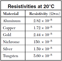
) is the resistivity of the material the object is made out of, in ohm*meters (omega•m), L is the length of the object, in meters, and A is the cross-sectional area of the object, in meters squared. Note that a table of material resistivities for a constant temperature is given to you on the reference table!

Let’s try a sample problem calculating the electrical resistance of an object:

Question: A 3.50-meter length of wire with a cross-sectional
area of 3.14 × 10⁻⁶ m2 at 20° Celsius has a resistance of 0.0625 omega. Determine the resistivity of the wire and the material it is made out of.

Answer: Regents Physics resistivity solution

Ohm’s Law

Agenda:

  • Ohm’s Law
  • Ohm’s Law Lab

If resistance opposes current flow, and potential difference promotes current flow, it only makes sense that these quantities must somehow be related. George Ohm studied and quantified these relationships for conductors and resistors in a famous formula now known as Ohm’s Law:

Ohm's Law

Ohm’s Law may make more qualitative sense if we re-arrange it slightly:

Regents Physics Ohms Law 2

Now it’s easy to see that the current flowing through a conductor or resistor (in amps) is equal to the potential difference across the object (in volts) divided by the resistance of the object (in ohms). If you want a large current to flow, you would require a large potential difference (such as a large battery), and/or a very small resistance.

Question: The current in a wire is 24 amperes when connected to a 1.5 volt battery. Find the resistance of the wire.

Answer: Regents Physics Ohms Law Solution

Regents Physics Ohm's Law Graph

Note: Ohm’s Law isn’t truly a law of physics — not all materials obey this relationship. It is, however, a very useful empirical relationship that accurately describes key electrical characteristics of conductors and resistors. One way to test if a material is ohmic (if it follows Ohm’s Law) is to graph the voltage vs. current flow through the material. If the material obeys Ohm’s Law, you’ll get a linear relationship, and the slope of the line is equal to the material’s resistance.

Introduction to Current Electricity

image

Flow of Charge

Regents Physics Waterfall Cascade

Electric current is the flow of charge, much like water currents are the flow of water molecules. Water molecules tend to flow from areas of high gravitational potential energy to low gravitational potential energy. Electric currents flow from high electric potential to low electric potential. And the greater the difference between the high and low potential, the more current that flows!

In a majority of electric currents, the moving charges are negative electrons. However, due to historical reasons dating back to Ben Franklin, we say that conventional current flows in the direction positive charges would move. Although inconvenient, it’s fairly easy to keep straight if you just remember that the actual moving charges, the electrons, flow in a direction opposite that of the electric current. With this in mind, we can state that positive current flows from high potential to low potential, even though the charge carriers (electrons) actually flow from low to high potential.

Electric current (I) is measured in amperes (A), or amps, and can be calculated by finding the total amount of charge (deltaq), in Coulombs, which passes a specific point in a given time (t). Electric current can therefore be calculated as:

electric current

Question: A charge of 30 Coulombs passes through a 24-ohm resistor in 6.0 seconds. What is the current through the resistor?

Answer: Regents Physics Current Solution

image

Resistance

Electrical charges can move easily in some materials (conductors) and less freely in others (insulators), as we learned previously. We describe a material’s ability to conduct electric charge as conductivity. Good conductors have high conductivities. In similar fashion, we describe a material’s ability to resist the movement of electric charge using resistivity, symbolized with the Greek letter rho (rho). Resistivity is measured in ohm-meters, which are represented by the Greek letter omega multiplied by meters (omega•m). Both conductivity and resistivity are properties of a material.

Ball Lightning Sample:

Electrostatics Problem Solving

Agenda:
Review HW: Charges, Fields and Potential
Video: Electrostatics Review
HANDOUT: Cartoon Charges
HW: Charges, Fields and Potential Packet (due 2/11) –> Solutions below

EXAM: P1, 4, 7 on Friday         P8/9 on Thursday

image

image

image

Electric Potential Difference

Reminder: P1, 4, 7 Exam 2/11; P9 Exam 2/10

 
Electric Potential Difference

When we lifted an object against the force of gravity by applying a force over a distance, we did work to give that object gravitational potential energy. The same concept applies to electric fields as well. If you move a charge against an electric field, you must apply a force for some distance, therefore you do work and give it electrical potential energy. The work done per unit charge in moving a charge between two points in an electric field is known as the electric potential difference, (V). The units of electric potential are volts, where a volt is equal to 1 Joule per Coulomb. Therefore, if you did 1 Joule of work in moving a charge of 1 Coulomb in an electric field, the electric potential difference between those points would be 1 volt. This is given to you in the reference table as:

Potential Difference

V in this formula is potential difference (in volts), W is work or electrical energy (in Joules), and q is your charge (in Coulombs). Let’s take a look at a sample problem.

Question: A potential difference of 10.0 volts exists between two points, A and B, within an electric field. What is the magnitude of charge that requires 2.0 × 10⁻² joule of work to move it from A to B?

Answer: Charge equals Work over Voltage

When dealing with electrostatics, often times the amount of electric energy or work done on a charge is a very small portion of a Joule. Dealing with such small numbers is cumbersome, so physicists devised an alternate unit for electrical energy and work that can be more convenient than the Joule. This unit, known as the electron-volt (eV), is the amount of work done in moving an elementary charge through a potential difference of 1V. One electron-volt, therefore, is equivalent to one volt multiplied by one elementary charge (in Coulombs): 1 eV = 1.6*10-19 Joules.

Question: A charge of 2*10-3 C is moved through a potential difference of 10 volts in an electric field. How much work, in electron-volts, was required to move this charge?

Answer: Electron Volt Calculation

Parallel Plates

If you know the potential difference between two parallel plates, you can easily calculate the electric field strength between the plates. As long as you’re not near the edge of the plates, the electric field is constant between the plates, and its strength is given by:

Electric Field Between Parallel Plates

You’ll note that with the potential difference V in volts, and the distance between the plates in meters, units for the electric field strength are volts per meter [V/m]. Previously, we stated that the units for electric field strength were newtons per Coulomb [N/C]. It is easy to show that these units are equivalent:

electrical_units_equivalence

Question: Which electrical unit is equivalent to one joule?

  1. volt / meter
  2. ampere * volt
  3. volt / Coulomb
  4. Coulomb*volt

Answer: (4) Coulomb*volt

Unit Conversion Answer

Let’s try another sample problem:

Parallel Plates

Question: The diagram represents two electrons, e1 and e2, located between two oppositely charged parallel plates. Compare the magnitude of the force exerted by the electric field on e1 to the magnitude of the force exerted by the electric field on e2.

Answer: The force is the same because the electric field is the same for both charges, as the electric field is constant between two parallel plates.

Equipotential Lines

Equipotential Lines

Much like looking at a topographic map which shows you lines of equal altitude, or equal gravitational potential energy, we can make a map of the electric field and connect points of equal electrical potential. These lines, known as equipotential lines, always cross electrical field lines at right angles, and show positions in space with constant electrical potential. If you move a charged particle in space, and it always stays on an equipotential line, no work will be done.

Electric Field

image


Notes:  Electrostatics Exam for P1, 4, 7 on 2/11; Exam for P8/9 on 2/10.


Electric Fields

Also similar to gravity, the electrostatic force is a non-contact force. Charged objects do not have to be in contact with each other to exert a force on each other. Somehow, a charged object feels the effect of another charged object through space. The property of space that allows a charged object to feel a force is a concept called electric field. Although we cannot see an electric field, we can detect its presence by placing a positive test charge at various points in space and measuring the force the test charge feels.

While looking at gravity, the gravitational field strength was the amount of force obsered by a mass per unit mass. The electric field strength is the amount of electrostatic force observed by a charge per unit charge. Therefore, the electric field strength, E, is the electrostatic force observed at a given point in space divided by the test charge itself. Electric field strength is measured in Newtons per Coulomb (N/C).

Electric Field Strength


Electric Field Lines

Since we can’t actually see the electric field, we can draw electric field lines to help us visualize the force a charge would feel if placed at a specific position in space. To help us visualize the electric field, we can draw electric field lines in space. These lines show the direction a positive charged particle would feel a force if it were placed at that point in space. The more dense the lines are, the stronger the force a charged particle would feel, therefore the stronger the electric field. As the lines get further apart, the strength of the electric force a charged particle would feel is smaller, therefore the electric field is smaller.

By convention, we draw electric field lines showing the direction of force on a positive charge. Therefore, to draw electric field lines for a system of charges, follow these basic rules:

  1. Electric field lines point away from positive charges, and toward negative charges.
  2. Electric field lines never cross.
  3. Electric field lines always intersect conductors at right angles to the surface.
  4. Stronger fields have closer lines.
  5. Field strength and line density decreases as you move away from the charges.

Let’s take a look at a few examples of electric field lines, starting with isolated positive (left) and negative (right) charges. Notice that for each charge, the lines radiate outward or inward spherically. The lines point away from the positive charge, since a positive test charge placed in the field (near the fixed charge) would feel a repelling force. The lines point in toward the negative fixed charge, since a positive test charge would feel an attractive force.

IndividualEFields

If you have both positive and negative charges in close proximity, you follow the same basic procedure:

Regents Physics Electric Fields


Comparing Electrostatics & Gravity

Because gravity and electrostatics have so many similarities, let’s take a minute to do a quick comparison of electrostatics and gravity.

image

Inverse Square Law

The big difference between electrostatics and gravity? The gravitational force can only attract, while the electrostatic force can both attract and repel. Notice again that both the electric field strength and the gravitational field strength follow the inverse-square law relationship. Field strength is inversely related to the square of the distance.