Circuit Analysis
Developing an understanding of circuits is the first step in learning about the modern-day electronic devices that dominate what is becoming known as the "Information Age." A basic circuit type, the series circuit, is a circuit in which there is only a single current path. Kirchhoff's Laws provide us the tools in order to analyze any type of circuit.
Kirchhoff's Laws
Kirchhoff's Current Law (KCL), named after German physicist Gustav Kirchhoff, states that the sum of all current entering any point in a circuit has to equal the sum of all current leaving any point in a circuit. More simply, this is another way of looking at the law of conservation of charge.
Kirchhoff's Voltage Law (KVL) states that the sum of all the potential drops in any closed loop of a circuit has to equal zero. More simply, KVL is a method of applying the law of conservation of energy to a circuit.
Question: A 3.0-ohm resistor and a 6.0-ohm resistor are connected in series in an operating electric circuit. If the current through the 3.0-ohm resistor is 4.0 amperes, what is the potential difference across the 6.0-ohm resistor?
Answer: First, let's draw a picture of the situation. If 4 amps of current is flowing through the 3-ohm resistor, then 4 amps of current must be flowing through the 6-ohm resistor according to Kirchhoff's Current Law. If we know the current and the resistance, we can calculate the voltage drop across the 6-ohm resistor using Ohm's Law:
Resistors in Series
Let's take a look at a sample circuit, consisting of three 2000-ohm (2K![]() ) resistors:
) resistors:
There is only a single current path in the circuit, which travels through all three resistors. Instead of using three separate 2K resistors, we could replace the three resistors with one single resistor having an equivalent resistance. To find the equivalent resistance of any number of series resistors, we just add up their individual resistances:
Note that because there is only a single current path, the same current must flow through each of the resistors.
VIRP Tables
A simple and straightforward method for analyzing circuits involves creating a VIRP table for each circuit you encounter. Combining your knowledge of Ohm's Law, Kirchoff's Current Law, Kirchoff's Voltage Law, and equivalent resistance, you can use this table to solve for the details of any circuit.
A VIRP table describes the potential drop (V-voltage), current flow (I-current), resistance (R) and power dissipated (P-power) for each element in your circuit, as well as for the circuit as a whole. Let's use our circuit with the three 2000-ohm resistors as an example to demonstrate how a VIRP table is used. To create the VIRP table, we first list our circuit elements, and total, in the rows of the table, then make columns for V, I, R, and P:
| V | I | R | P | |
|---|---|---|---|---|
| R1 | ||||
| R2 | ||||
| R3 | ||||
| Total |
Next, we fill in the information in the table that we know. For example, we know the total voltage in the circuit (12V) provided by the battery, and we know the values for resistance for each of the individual resistors:
| V | I | R | P | |
|---|---|---|---|---|
| R1 | 2000 |
|||
| R2 | 2000 |
|||
| R3 | 2000 |
|||
| Total | 12V |
Once we have our initial information filled in, we can also calculate the total resistance, or equivalent resistance, of the entire circuit. In our case, this is 6000 ohms:
| V | I | R | P | |
|---|---|---|---|---|
| R1 | 2000 |
|||
| R2 | 2000 |
|||
| R3 | 2000 |
|||
| Total | 12V | 6000 |
If I look at the bottom (total) row of my table, I know both the voltage drop (V) and the resistance (R). Knowing these two items, I can calculate the total current flow in the circuit using Ohm's Law, and I can also calculate the total power dissipated in the circuit using my formulas for electrical power:
I can now fill in more information in the VIRP table:
| V | I | R | P | |
|---|---|---|---|---|
| R1 | 2000 |
|||
| R2 | 2000 |
|||
| R3 | 2000 |
|||
| Total | 12V | 0.002A | 6000 |
0.024W |
Because this is a series circuit, the total current has to be the same as the current through each individual element, so I can fill in the current through each of the individual resistors:
| V | I | R | P | |
|---|---|---|---|---|
| R1 | 0.002A | 2000 |
||
| R2 | 0.002A | 2000 |
||
| R3 | 0.002A | 2000 |
||
| Total | 12V | 0.002A | 6000 |
0.024W |
Finally, for each element in the circuit I now know the current flow and the resistance. Using this knowledge, I can apply Ohm's Law to obtain the voltage drop (V=IR), and a formula for power (P=I2R) to complete the table.
| V | I | R | P | |
|---|---|---|---|---|
| R1 | 4V | 0.002A | 2000 |
0.008W |
| R2 | 4V | 0.002A | 2000 |
0.008W |
| R3 | 4V | 0.002A | 2000 |
0.008W |
| Total | 12V | 0.002A | 6000 |
0.024W |
So what does this table really tell us now that it's completely filled out? We know the potential drop across each resistor (4V), the current through each resistor (2 mA), and the power dissipated by each resistor (8 mW). In addition, we know the total potential drop for the entire circuit is 12V, and the entire circuit dissipated 24 mW of power. Note that for a series circuit, the sum of the individual voltage drops across each element equal the total potential difference in the circuit, the current is the same throughout the circuit, and the resistances and power dissipated values also add up to the total resistance and total power dissipated. These are summarized for you on your reference table as follows: 
Sample Problem
Parallel Circuits
Another basic circuit type is the parallel circuit, in which there is more than one current path. To analyze resistors in a series circuit, we found an equivalent resistance. We'll follow the same strategy in analyzing resistors in parallel.
Resistors in Parallel
Let's look at a circuit made of the same components we used in our exploration of series circuits, but now we'll connect our components so as to provide multiple current paths, creating a parallel circuit.
Notice that in this circuit, electricity can follow one of three different paths through each of the resistors. In many ways, this is similar to a river branching into three different smaller rivers. Each resistor, then, causes a potential drop (analogous to a waterfall), then the three rivers recombine before heading back to the battery, which we can think of like a pump, raising the river to a higher potential before sending it back on its looping path.
We can find the equivalent resistance of resistors in parallel using the formula:
Take care in using this equation, as it's easy to make errors in performing your calculations. Let's see if we can find the equivalent resistance for our sample circuit.
Circuit Analysis
We can once again utilize a VIRP table to analyze our circuit, beginning by filling in what we know directly from the circuit diagram.
| V | I | R | P | |
|---|---|---|---|---|
| R1 | 2000 |
|||
| R2 | 2000 |
|||
| R3 | 2000 |
|||
| Total | 12V |
We can also see from the circuit diagram that the potential drop across each resistor must be 12V, since the ends of each resistor are held at a 12V difference by the battery.
| V | I | R | P | |
|---|---|---|---|---|
| R1 | 12V | 2000 |
||
| R2 | 12V | 2000 |
||
| R3 | 12V | 2000 |
||
| Total | 12V |
Next, we can fill in the current through each of the individual resistors since we know the voltage drop across each resistor using Ohm's Law (I=V/R) to find I=0.006A.
| V | I | R | P | |
|---|---|---|---|---|
| R1 | 12V | 0.006A | 2000 |
|
| R2 | 12V | 0.006A | 2000 |
|
| R3 | 12V | 0.006A | 2000 |
|
| Total | 12V |
Using Kirchhoff's Current Law, we can see that if 0.006A flows through each of the resistors, these currents all come together to form a total current of 0.018A.
| V | I | R | P | |
|---|---|---|---|---|
| R1 | 12V | 0.006A | 2000 |
|
| R2 | 12V | 0.006A | 2000 |
|
| R3 | 12V | 0.006A | 2000 |
|
| Total | 12V | 0.018A |
Because each of the three resistors has the same resistance, it only makes sense that the current would be split evenly between them. And we can confirm our earlier calculation about the equivalent resistance by calculating the total resistance of the circuit using Ohm's Law: ![]() .
.
| V | I | R | P | |
|---|---|---|---|---|
| R1 | 12V | 0.006A | 2000 |
|
| R2 | 12V | 0.006A | 2000 |
|
| R3 | 12V | 0.006A | 2000 |
|
| Total | 12V | 0.018A | 667 |
Finally, we can finish our VIRP table using any of the three applicable equations for power dissipation to find:
| V | I | R | P | |
|---|---|---|---|---|
| R1 | 12V | 0.006A | 2000 |
0.072W |
| R2 | 12V | 0.006A | 2000 |
0.072W |
| R3 | 12V | 0.006A | 2000 |
0.072W |
| Total | 12V | 0.018A | 667 |
0.216W |
Note that for resistors in parallel, the equivalent resistance is always less than the resistance of any of the individual resistors. The potential difference across each of the resistors in parallel is the same, and the current through each of the resistors adds up to the total current. This is summarized for you on the reference table:
Sample Problems
Let's take a look at a basic parallel circuit analysis problem:
In similar fashion, we should also be able to construct circuit diagrams from descriptions of the circuit:
Let's take a look at a final sample problem, this time involving the use of ammeters in the analysis of our parallel circuit:
Combination Series-Parallel Circuits
A circuit doesn’t have to be completely serial or parallel. In fact, most circuits actually have elements of both types. Analyzing these circuits can be accomplished using the fundamentals you learned in analyzing series and parallel circuits separately and applying them in a logical sequence.
First, look for portions of the circuit that have parallel elements. Since the voltage across the parallel elements must be the same, replace the parallel resistors with an equivalent single resistor in series and draw a new schematic. Now you can analyze your equivalent series circuit with a VIRP table. Once your table is complete, work back to your original circuit using KCL and KVL until you know the current, voltage, and resistance of each individual element in your circuit.
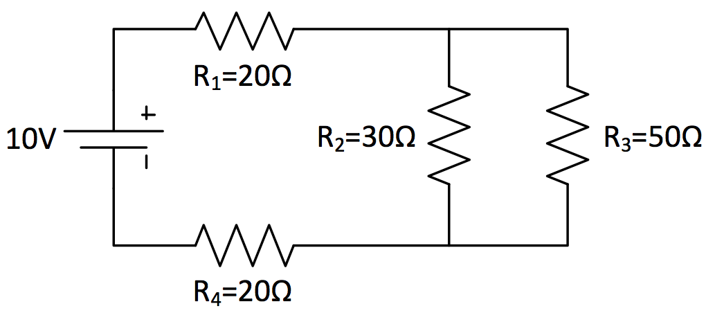
Question: Find the current through R2 in the circuit below.
Answer: First, find the equivalent resistance for R2 and R3 in parallel.
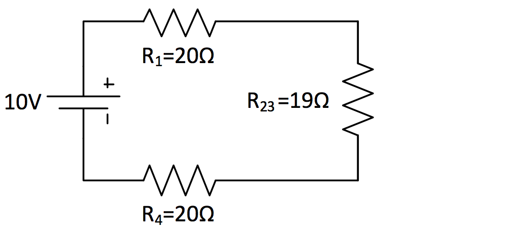
Next, re-draw the circuit schematic as an equivalent series circuit.
Now, you can use your VIRP table to analyze the circuit.
VIRP Table V I R P R1 3.39V 0.169A 20 0.57W R23 3.22V 0.169A 19 0.54W R4 3.39V 0.169A 20 0.57W Total 10V 0.169A 59 1.69W
The voltage drop across R2 and R3 must therefore be 3.22 volts. From here, you can apply Ohm’s Law to find the current through R2: