Electrical Meters
Voltmeters
Voltmeters are tools used to measure the potential difference between two points in a circuit. The voltmeter is connected in parallel with the element to be measured, meaning an alternate current path around the element to be measured and through the voltmeter is created. You have connected a voltmeter correctly if you can remove the voltmeter from the circuit without breaking the circuit. In the diagram at right, a voltmeter is connected to correctly measure the potential difference across the lamp. Voltmeters have very high resistance so as to minimize the current flow through the voltmeter and the voltmeter's impact on the circuit.
Ammeters
Ammeters are tools used to measure the current in a circuit. The ammeter is connected in series with the circuit, so that the current to be measured flows directly through the ammeter. The circuit must be broken to correctly insert an ammeter. Ammeters have very low resistance to minimize the potential drop through the ammeter and the ammeter's impact on the circuit, so inserting an ammeter into a circuit in parallel can result in extremely high currents and may destroy the ammeter. In the diagram at right, an ammeter is connected correctly to measure the current flowing through the circuit.
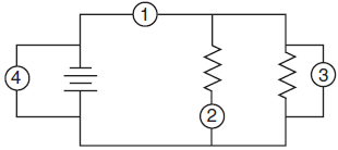
Question: In the electric circuit diagram at right, possible locations of an ammeter and a voltmeter are indicated by circles 1, 2, 3, and 4. Where should an ammeter be located to correctly measure the total current and where should a voltmeter be located to correctly measure the total voltage?
Answer: To measure the total current, the ammeter must be placed at position 1, as all the current in the circuit must pass through this wire, and ammeters are always connected in series.
To measure the total voltage in the circuit, the voltmeter could be placed at either position 3 or position 4. Voltmeters are always placed in parallel with the circuit element being analyzed, and positions 3 and 4 are equivalent because they are connected with wires (and potential is always the same anywhere in an ideal wire).
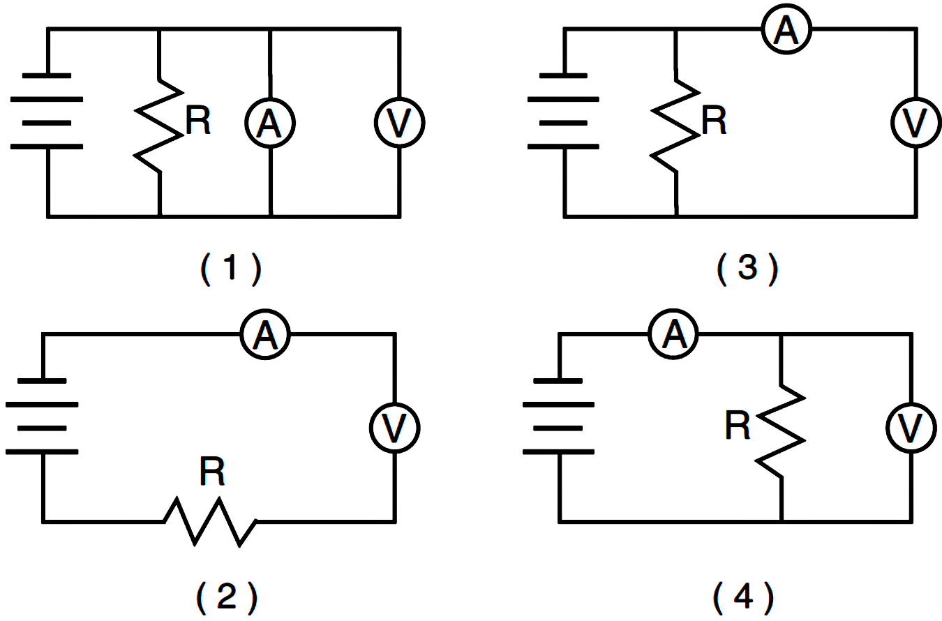
Question: Which circuit diagram below correctly shows the connection of ammeter A and voltmeter V to measure the current through and potential difference across resistor R?
Answer: (4) shows an ammeter in series and a voltmeter in parallel with the resistor.
Question: Compared to the resistance of the circuit being measured, the internal resistance of a voltmeter is designed to be very high so that the meter will draw
- no current from the circuit
- little current from the circuit
- most of the current from the circuit
- all the current from the circuit
Answer: (2) the voltmeter should draw as little current as possible from the circuit to minimize its effect on the circuit, but it does require some small amount of current to operate.